
Introduction
At the bedrock of every embedded device lies the communication interface to the outside world. This communication interface is what is used to pass the data collected by the MCU to the relevant consumers. There are several communication interfaces (UART, I2C, SPI…) etc.
You can know the protocol and how it works, and manage to make it work no problem, but to go further, we need to visualize the communicated data somehow to verify that the protocol being decoded is right and if we encounter any error in our firmware, then we can pinpoint the source of the problem.
This article is going to debunk to some detail my escapades in investigating the ins of these protocols. THough not very detailed, I explain some technical prts on how to set up a analyzer and get some useful data from it (at least).
Why?
One of the reasons why visualizing data/packets sent over a protocol is crucial is three-fold:
- Ensure the full packet is being received by the consumer
Sometimes packet data is split by too many gaps, causing a timeout in the parsing logic. You might also find that the start and stop bits are not as expected, which causes a framing error. Another thing you can verify here is the CRC and checksums being used to confirm that data integrity holds across transmissions
- Check if the packet being transmitted by the producer is correct
Here we need to validate the sender’s behaviour. Sometimes the firmware is correct and it thinks it sent the right data, but what matters is what logic level actually left the pin. As the above, you can confirm CRC/checksums, framing, addresses etc. Also you can verify baud rate, bit timing, and incomplete frames
- Determine which protocol is being used to send the packet. This is mainly used for reverse engineering
In cases where the protocol is unclear, we can identify the protocol being used by visualizing the clock/data relationships, edges etc. For example with UART we can easily identify the start and stop bit to know that it is actually UART. Here, we can decode unknown messages into HEX patterns that can then be mapped into real-world meaning.
UART basic case scenario
In this first case, I am going to show you how to simply visualise a message being sent by an STM32 MCU via UART with a logic analyzer. (Note that any other MCU will suffice).
Requirements
- STM32 MCU
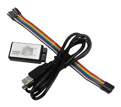
- Any logic analyser
Am using STM32F407VGT6 MCU and a clone Saleae Logic Analyzer with 8 channels and 24MHz bandwidth.
Connection
- Connect GND pin of the logic analyzer to GND pin of the MCU
- Connect CH1 pin to TX pin of the MCU
UART code
The following snippet shows the initialization part of UART logic. Here I create a simple buffer to hold the message being transmitted to the consumer. We are going to visualize this message.
/* USER CODE BEGIN 0 */
#define BUFFER_SIZE 1024
char buffer[BUFFER_SIZE] = {0};
/* USER CODE END 0 */
Next I create the message using snprintf. snprintf is safer than sprintf because you can detect truncation and it automatically appends a NUL terminator at the end of the string.
/* USER CODE BEGIN 2 */
 int len = snprintf(buffer, sizeof(buffer), "%s\r\n", "HELLO STM32");
 /* check for overflow */
 if(len >= sizeof(buffer)) {
	  /*todo: handle overflow*/
 }
 /* USER CODE END 2 */
Then in the superloop, I call HAL_UART_Transmit to with a blocking delay of half-a-second.
while (1)
 {
   /* USER CODE END WHILE */
   /* USER CODE BEGIN 3 */
	  HAL_UART_Transmit(&huart1, (uint8_t*)buffer, strlen(buffer), 1000);
	  HAL_Delay(500);
 }
 /* USER CODE END 3 */
I am running Logic 2 analyzer software which officially comes from Saleae to be used with their logic analysers. You can view or download it here:
https://www.saleae.com/pages/downloads
Viewing the signal
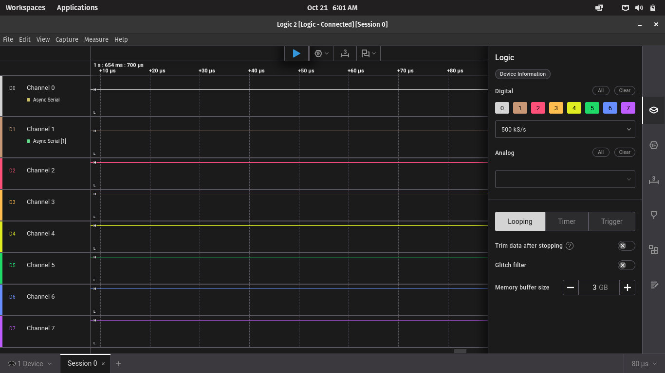
- Once you start the software it will automatically detect the logic analyser device.
- All the channels will be shown but you can hide each channel selectively
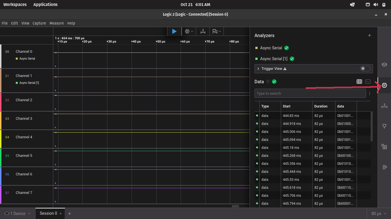
- To choose the protocol, click on analyzers and click the + icon.
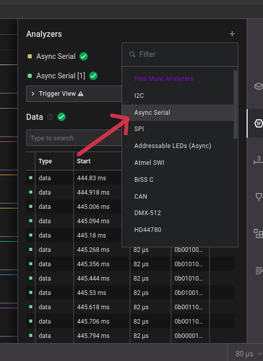
Selecting analyzer view
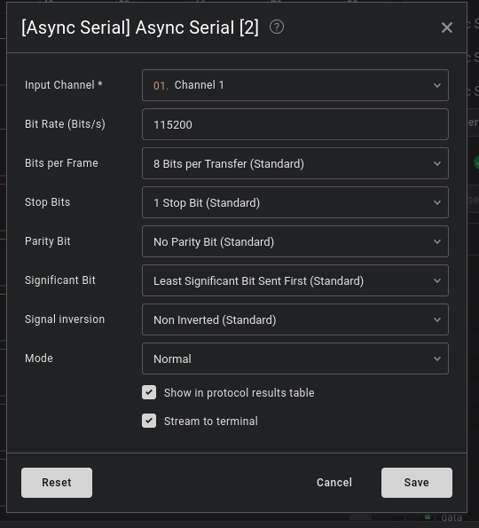
- Then select Async Serial
- Select the channel and configure the UART settings according to your settings on the MCU. Then click save.
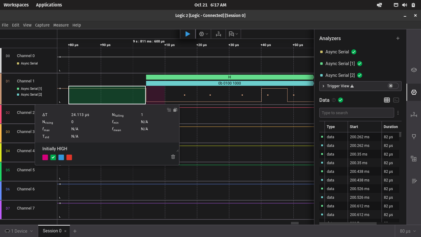
- With your firmware running, click on the START(R) icon to capture the signal. You will see the image with samples like the one shown here.
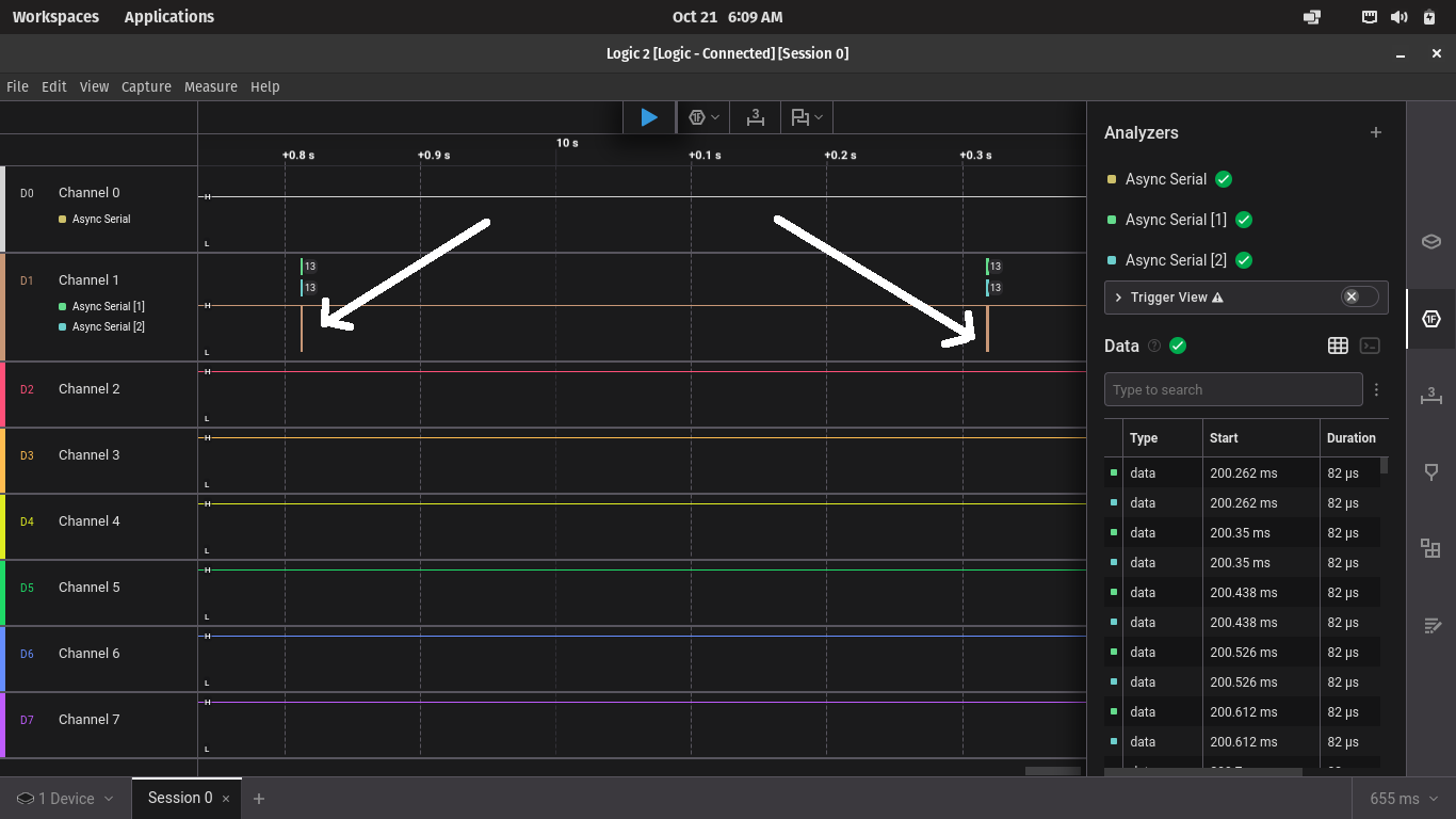
- Zoom into the image with the mouse wheel and you will be able to see the packet signal.
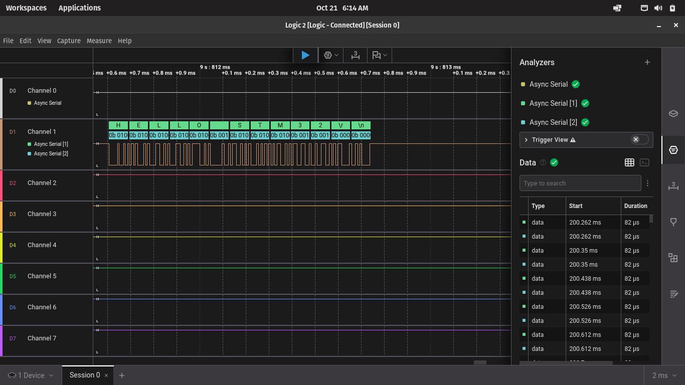
- selecting either HEX, ASCII, DEC etc. Selecting ASCII will display the exact characters sent from the MCU
Okay. But what does this mean? Decoding
Now that we have the signal, let’s see how we can decode some of the information embedded in it.
Start and Stop bit
Since this is a UART signal, the first thing to check is the start and stop bit.
If you zoom in on the beginning of the signal, you should be able to see that the signal is initially HIGH, then it is pulled LOW for some bit time. See the image below:
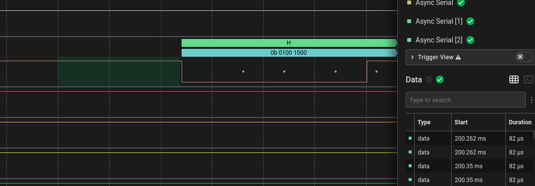
The image below shows how the start bit is activated:
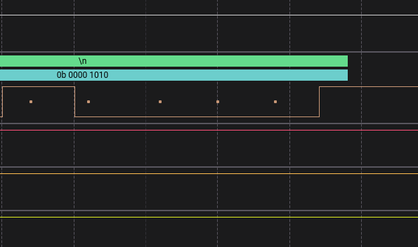
Stop bit
A stop bit is typically simply indicated by pulling the line HIGH for some time after the message packet is done transmitting. You can see in the image below that after \n is done being sent, there is a short bit of time after that to indicate the stop bit.
The image below shows the stop bit:
Byte order
UART protocol transmits the data as LSB first. This means that the first byte seen on the waveform is the Least Significant Bit. It may seem counter intuitive that the displayed char is in reverse. The software displays the correct char but when you are reading the binary data/value, the first bit you read will always be LSB for UART.
In the next article we will analyze the I2C protocol by visualizing its waveforms.
Conclusion
This article summarised a method to use a basic Logic Analyser to decode UART signals. We explored the setup using the Logic2 software on PC, and decoded a simple UART message to determine information such as start bit, stop bit, baud rate, and the actual transmitted message.
Meanwhile, keep tinkering!