
Hi. So I am in the middle of design and development of Project Shadow Flight (A simple 1U cubesat for you newcomers), and I thought I write a super short article on how the system integration is done and my design approach, moreso the connection method I am using mate all the PCBs together.
A little background
The ISA (Industry Standard Architecture)
Careful research dates back to the 80s when network interface cards and motherboards were hitting the ground at fast pace(IBM PCs). Standards had to be designed to ensure everyone conforms to the same wiring so that systems from different manufacturers could be used together, and make it easy to upgrade/maintain/repair PCs, ensuring hardware modularity, a critical hardware design architecture.
This led to the ISA standard that defines the pins and pin assignment for the connectors used. These connectors are called the ISA connectors. The image below shows that:
Source: http://www.controllersandpcs.de/Project_sources/ISA_Base14a_reference.pdf
As is visible, the ISA connector is used for mating two different boards together, let’s say a daughterboard and a motherboard. The daughter board can be e.g. a Network Interface Card. The motherboard implements the ISA connector and standard, whose pins are known beforehand such that the moment you insert the daughter-board, everything works as it should. This is the classic plug-and-play structure.
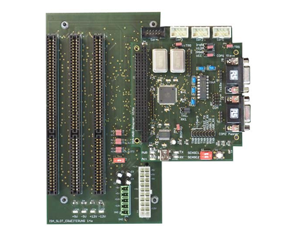
Looking at the board below, you can see that the motherboard implements 3 ISA connector slots:
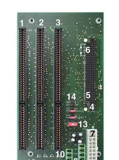
Source: http://www.controllersandpcs.de/Project_sources/ISA_Base14a_reference.pdf
The ISA is a super robust standard that implements either 8/16 bit data bus and a 24 bit address bus, plus control lines e.g IRQs, RW, WR, DMA etc. (I won’t go into details). You can read more about it here: https://pc104.org/wp-content/uploads/2015/02/PC104_Spec_v2_6.pdf
Connector types
How to connect the boards together? There are 2 options:
- ISA slots
- PC/104
ISA slots are nothing but connectors that allow a board with gold-fingers to be inserted into them. The image below shows a network interface card with gold fingers that can easily mate with an ISA connector.
However, the disadvantage with ISA connector is that it is not so rugged and robust enough physically. If the motherboard is shaken by some strong enough vibration, the daughterboard is bound to fall off.
This is where PC/104 comes in. PC/104 is a connector type that follows the same ISA standard(pin assignment), but the connector is in such a way that the boards can be stacked on top of each other.
The PC/104 connector has both male and female connectors in such a way that the bottom on one board can be inserted onto the top of the next, such that the PCBs appear stacked.
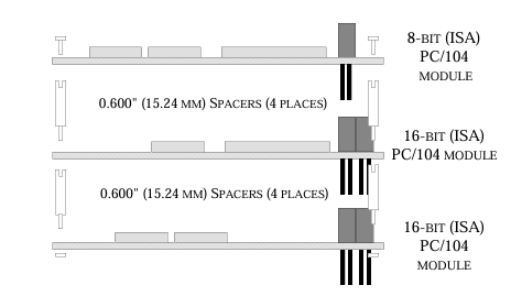
This is more robust and rugged. In addition, it occupies minimal space without the need for a huge backplate (motherboard), therefore reducing space.
Space is premium especially in highly critical systems, for example ….. You guessed it ….cubesats! So looking forward, I presume the more space you occupy in a rideshare program during launch the more you pay? PC/104 has a size limit for boards (90 x 96mm), which is why 1U cubesats maintain PCB dimensions of at most 100x100mm.
Usage in my cubesat
Now, I am not developing a PC here. So I do not need the ISA standard. What I need is the ISA connector type, specifically the PC/104. We are allowed to use the connector but then define our own pin assignment to the connector. For example the image below shows a snippet of one of my schematics, the PC/104 connector part.
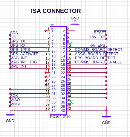
As seen, since these PCBs will be stacked on top of each other, it means that the signals are shared across the whole PCB stack, allowing me to route relevant signals from one board to the next. For example I am using teh ADCS board only to read sensors, since it has no dedicated MCU, I route the collected data via PC/104 to OBC for processing.
Additionaly, one feature I have on my cubesat is that the OBC can tell when one or more boards are not inserted into the stack. To do this, I place a simple resistor that pulls a pin to ground on every board. (see below).
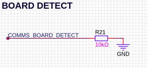
When a board is inserted, this pin can be monitored by the OBC to ensure features are activated only if the board exists. (mainly for testing).
Conclusion
Yeah. That’s the little and much to it that I could write without making this article too long (and boring). For more info you can visit the project docs here:
https://bytecod3.github.io/Project-Shadow-Flight/
See you later.
References
- http://www.controllersandpcs.de/Project_sources/ISA_Base14a_reference.pdf
- https://pc104.org/wp-content/uploads/2015/02/PC104_Spec_v2_6.pdf