Introduction
Recently, out of curiosity to get my fundamentals right, I have been investigating the most common hardware design patterns used in building common industrial equipments, along the way, especially regarding the control electronics there-of, I have realized that the best way to implement a “complex” system is to leverage the most basic systems and concepts, coupled together in ingenious methods . In this article, I am going to provide a high-level debunking of how the most fundamental laws in electronics, Ohm’s Law and Kirchoff’s Current Law, are used in designing some of the most robust industrial equipment communication loops, allowing for continued reliability during operation, critical in industrial equipment. I will discuss how the 4-20mA loop works. Why it is used, its origin and we will explain why and how this design powers heavy data 2-wire acquisition instruments without fail.
Ohms Law
The fact that you are reading this article means that at least you have a background in electronics, I assume. The fundamental law in electronics is the Ohm’s Law, which is basically V=IR, in words, “the current through two points on a conductor is directly proportional to the voltage drop across the two points”. From this law, the voltage, resistance or current can be derived if any other two values are known.
Kirchoff's current law
At any node (junction) in an electrical circuit, the algebraic sum of currents is zero; equivalently, the total current entering the node is equal to the total current leaving the node. Simply, current through the loop remains the same.
It is these 2 laws that 4-20mA loops are designed from.
Problem background
There are 2 things that you need to optimize in an industrial setting.
- Power usage
- Signal/data integrity
Consider this case. You have ~500m on a factory floor, with an instrument at the first end and the other at the farthest end, so basically a distance of 500m between the two instruments. Let’s suppose the two instruments use a 24VDC supply to run. You have decided to have a single point supply, 24VDC source, with a 24VDC cable running to the first instrument and the other to the last instrument. The problem with this architecture is that by the time 24VDC gets to the last instrument, the voltage will have dropped, simply because the conductor is long and based on physics, every conductor has a resistivity factor, which is a function of the conductor’s length. And since the voltage has to travel back to the source, this makes it a ~1000m round trip.
In addition, the instrument is reading a sensor and data is expected to be transmitted to a PLC or a distributed data acquisition system. Well, this is easy to solve; use a protocol that supports such distances, for instance ModBus RTU. But suppose you have an instrument type that does not support ModBus RTU, and you need process/signal data back to your DAQ system (PLCs or Distributed)
To add to this mix, most factory floors are noisy, with AC motors, low frequency noise, spikes from solenoids etc. The operating environment is best described as a combination of challenging conditions, all arriving at once. Phewks!
Well, let us see whether we can solve this.
Enter current loops
Now. Think about it. If voltage is dependent on the conductor length, it is well known that the current in a loop stays the same, regardless of the voltage drop across the components. In other words this means that it is easier to control current, which will not drop, than it is to control voltage. The magnitude of current that flows from the source is the same magnitude of current that will flow back to the source.
Why 4-20mA
I will avoid a lot of history, but 4-20mA originates partly from pneumatic transmissions in the 1950s. Pneumatic transmissions were used to control large compressors in the range of 3psi to 15psi. These pneumatic lines connected to pneumatically controlled valves in order to control actuators across the buildings, all from compressed air. In this way, the modern 4-20mA signal emulates these systems.
But why 4mA? What is this value? Let me try to explain this simply. Assume you have a loop that uses 0-20mA. If the sensor reads a full-scale value, you will transmit 20mA, which can easily be measured. No problem about that. But when the sensor measures a value of 0, the transmitted value will be 0, your receiver will read a 0. The problem is you won't be able to distinguish whether the sensor is OFF/FAULTY or the reading is actually 0. So to solve this, the minimum reading is raised to 4mA. This way, if you read a value less than 4mA, then the sensor is faulty. This is also known as a live-zero. Further, if you have an actuator that uses 4-20mA in a control system, you can be sure that if you set the current to slightly below 4mA, say 3mA, your actuator is guaranteed to be completely OFF.
In addition, the practical current value that can provide enough transmitter power is 4mA, not 1mA or 2mA. This level is used to provide inherent power to the transmitter, explained shortly below.
But what are the advantages of using a 4-20mA loop?
The greatest advantage to using 4-20mA devices is the current loop’s low sensitivity to electrical noise. As mentioned above, this is very important for harsh industrial environments.
Secondly, Kirchoff’s current law says that the current flowing through a loop is essentially the same through every node in the loop. Current in is equal to current out.
2-Wire vs. 4-Wire instruments
Now there are two types of current loop instruments. 2-wire and 4-wire instruments. I will discuss 2-wire devices in this article. 4-wire devices will be pushed to a later article.
-
2-Wire devices
In this scheme, 2 wires are used to convert various process signals be it pressure, speed, position, temperature etc, to 4-20mA DC for the purpose of transmitting the signal over some distance with little or no loss of signal.
See diagram below:
The power supply is commonly a 24VDC. The current loop uses DC power because the magnitude of the current is what represents the signal level that is being transmitted. The power supply must always be set to a level higher than what is required by the transmitter, IR drop in the receiver and any IR drop in the transmission line.
The receiver is located at the other end of the transmission line, receiving this transmitted signal. The receiver in most cases is located a distance away from the transmitter. For most receiver devices, the loop current is commonly passed through a resistor to produce a voltage for measurement by the device. This voltage generated across the internal resistance of the receiver is what the receiver processes. Mostly precision resistors are what are used to convert the current to this voltage. Since the current flowing through the loop is the same, you can wire several receivers along the same line in series, as long as the power supply voltage is able to support these voltage drops.
The transmitter is considered to be the most important device in the loop. The transmitter acts as the component that regulates the current in the loop based on the magnitude of the acquired signal. Here, 4mA represents the zero input and 20mA represents the full-scale reading. In 2 wire transmitters, the operating power is drawn from the current flowing through them and the voltage across them. The implication of this is that since 4mA is the lowest voltage, the voltage produced from this must be sufficient to power the transmitter. Likewise, the voltage produced from 20mA max must not exceed the voltage that the transmitter can handle.
Example diagram of 3 Wired loops connected together
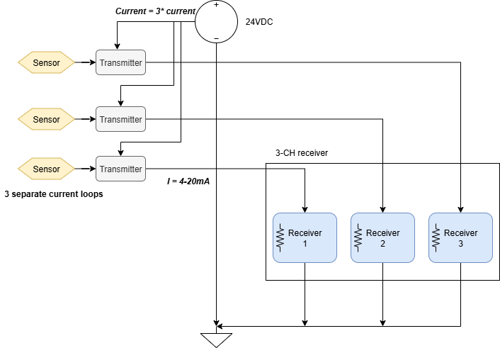
If you notice, the power supply must be rated to 3 times the maximum transmitter current, according to current division principle. Such an implementation must include some form of current-limiting and/or fault protection that limits the current and voltage to the transmitter.
Conclusion
In conclusion, the 4–20 mA current loop is an engineering solution optimized for long-distance, noisy industrial environments by leveraging the fundamental advantages of current transmission over voltage transmission. By relying on Kirchhoff’s Current Law, the loop ensures that the same current flows through all elements regardless of conductor resistance and voltage drop, making signal integrity largely independent of cable length over hundreds of meters. The choice of a 4 mA live zero, rather than 0 mA, enables clear fault detection, guarantees a defined “off” state for actuators, and provides sufficient quiescent power to operate loop-powered (two-wire) transmitters, while the 16 mA span up to 20 mA offers robust resolution and noise immunity. Rooted historically in 3–15 psi pneumatic systems, the 4–20 mA standard persists because it simultaneously addresses power delivery, diagnostics, electromagnetic interference, and interoperability, making it exceptionally well-suited for harsh factory-floor conditions and distributed process control systems.
References
2. https://resources.altium.com/p/how-to-design-a-4-20ma-current-loop-receiver-with-minimal-components